The latch is a temporary storage built from several logic gates. Logic gate is an electronic component that outputs the value 0 or 1 base on the input. There are many types of logic gates, for example, AND Gates, OR Gates, NOR Gates, NAND Gates, or NOR Gates, XOR Gates, etc. Do they confuse you? Don’t be panic.
To construct a latch, we may use either NOR Gates or NAND Gates. Let’s starts by talking about the NAND Gates. NAND Gates means NOT-AND.
Truth Table for AND and NAND
| Input 1 | Input2 | Output(AND) | Output(NAND) |
| 0 | 0 | 0 | 1 |
| 0 | 1 | 0 | 1 |
| 1 | 0 | 0 | 1 |
| 1 | 1 | 1 | 0 |
NAND’s output is opposed to the AND one.

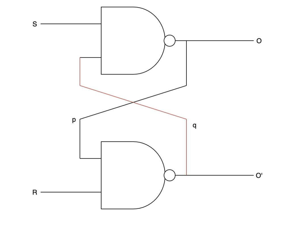
How to implement a Latch using NAND Gates?

Truth table for NAND type Latch
| S(Set) | R(Reset) | O(Output) | O’ |
| 0 | 0 | 1 | 1 |
| 0 | 1 | 1 | 0 |
| 1 | 0 | 0 | 1 |
| 1 | 1 | Keep Unchanged | Keep Unchanged |
But what is the principle here?
When S and R are both 0, the O and the wire p are 1. Then, the O’ and wire q are 1. This also leads O’ to be 1. However, in the Latch, O’ and O should not be in the same state. Therefore, This status is considered to be invalid.
When S is 0 and R is 1, O is 1. As wire p and input R is 1, O’ is 0.
When S is 1 and R is 0, O is 0. As wire p and input R is 0, O’ is 1.
When both S and R are 1, there is no change to wire p and wire q. Therefore, the state of O and O’ do not change. This is why this device can be used to store the data temporarily.
Now I am going to talk about the NOR type Latch.
| Input 1 | Input2 | Output(OR) | Output(NOR) |
| 0 | 0 | 0 | 1 |
| 0 | 1 | 1 | 0 |
| 1 | 0 | 1 | 0 |
| 1 | 1 | 1 | 0 |
NOR Gate’s logic is opposed to the OR one.

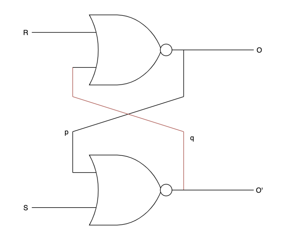
The NOR Gates are interconnected in this way.

The truth Table for NOR type Latch
| S(Set) | R(Reset) | O(Output) | O’ | Remark |
| 0 | 0 | Keep Unchanged | Keep Unchanged | Unchange |
| 0 | 1 | 0 | 1 | |
| 1 | 0 | 1 | 0 | |
| 1 | 1 | 0 | 0 | Invalid |
By Comparison, 1 is considered to be active in the NOR type Latch whereas 0 is considered to be active in the NAND type Latch.
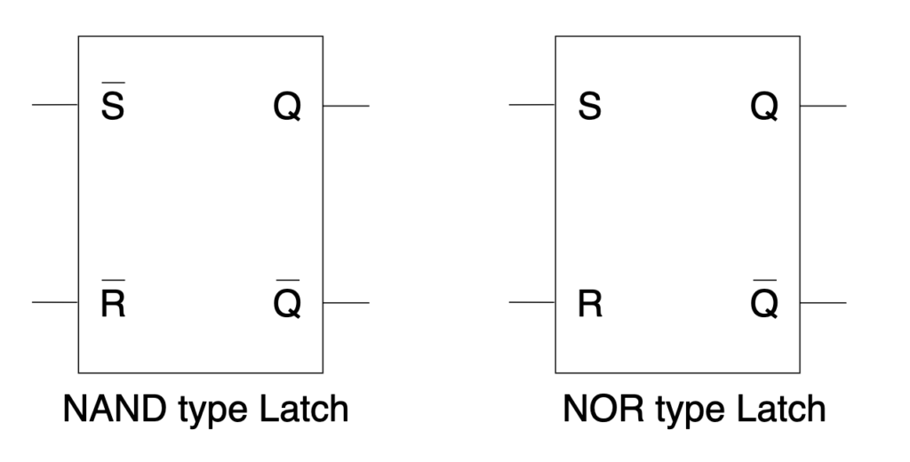
To represent the Latch, we may represent it in the following way!

When there is a bar on the top, it means that it is active low.
Also, to prevent the invalid status, we may add an inverter in the following way.

Also, we may add an enable pin to disable the input signal from amending the status of the latch.

Actually, these can be expressed as D-Flip-Flop

Next time, I will talk more about what can this D-latch use for!